
 notepad
![[updates]](https://eev.ee/theme/images/category-updates.png)

🔗 Particle wipe generator on itch or hosted locally
🔗 Source code
This is a tool for making particle wipes, a type of transition whose name I made up because I don’t think they have a well-known name! They can be used in Ren’Py, RPG Maker, or anything that lets you write a shader.
Most of my games have done screen transitions with simple fades, and I wanted to try something different here, but I couldn’t find a tool to make the effect I wanted. So I wrote my own. If you’re interested, here’s how it works:
The idea
I was inspired by two things. One is Cave Story’s transitions.
That looks rad, right? I think it does, anyway. I wanted to do something similar myself.
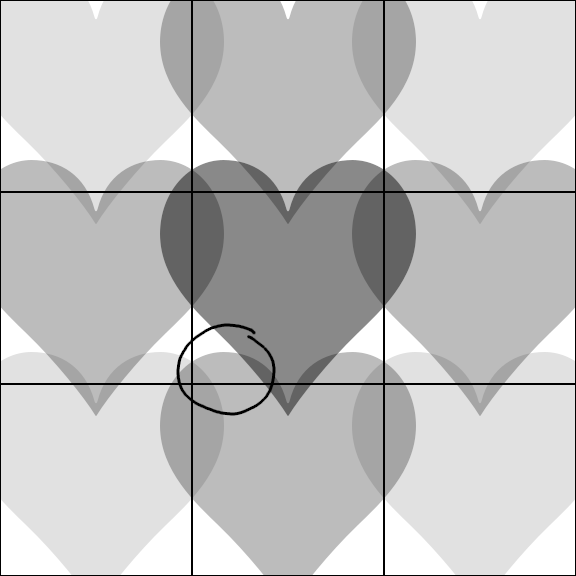
At a glance, this effect looks pretty simple. The screen is sliced into a grid. A diamond shape starts expanding from the center of each cell until the cell is filled. By staggering when each cell starts, you can make an animation that seems to wipe from the bottom upwards, or from the edges inwards, or who knows what else.
Here’s a frame from the above capture, showing the grid. You can see from the blocks near the middle that it’s the same as the tile grid.

Notice that Cave Story transitions either from a scene to a solid color, or vice versa. Offhand, I don’t think the game ever transitions directly between two scenes.
My guess is that it’s manually drawing solid color on top of the tilemap until the entire screen is obscured, switching maps in the background, then reversing the progress. The various sizes of diamond might even be physical sprites on a foreground layer!
That poses a slight problem for me, because I want to be able to transition directly between scenes as well. Enter inspiration number two: Ren’Py.
Ren’Py is a visual novel engine, and it supports a ton of screen transitions. That makes sense, since visual novels generally don’t have much animated art, so most of the animation happens in transitions and sprite effects.
One such transition is a generic one called ImageDissolve, which can do a mask transition (another term I made up). It takes a grayscale mask, which tells it the order to reveal pixels. Where the mask is black, the corresponding pixels of the “after” scene are shown almost immediately; where the mask is white, those “after” pixels are the last to appear.
(I suddenly realize that Ren’Py does that backwards, with white pixels being first, but that doesn’t make sense to be since black pixels are zero.)
That’s a bit of a mouthful to describe with text, so here’s a basic example. A linear gradient from black to white will play out as a straight wipe in the same direction.

This approach can capture any kind of transition where pixels are revealed in a given order, and if I implement it with a shader (which is very easy), I can emulate the Cave Story style without being limited to a solid color! Neat!
The problem
The problem is… how do I generate the mask image? I searched around a bit and found folks who’d made transitions for use with Ren’Py, but no explanation of how they did it.
Let me think about emulating Cave Story’s effect using the mask approach, one step at a time.
Forget about the wipe effect for now and concentrate on a single cell. When the diamond is just starting to appear, it should be black. When it completely fills the cell — i.e., when it’s big enough that its edges just barely touch the cell corners — it should be white. In the middle somewhere, it should be medium gray. Imagining (or drawing) a few cases suggests a simple diamond gradient, which seems correct.

Now for the wipe effect. All it really does is stagger when the animation starts. The upwards wipe, for example, starts animating all the cells on the bottom row, waits some short amount of time, then starts animating all the cells on the next row up, and so on. An ASCII diagram of this process (for a simplified, smaller screen) might look like:
 1   00 |                     XXXXXXXX
 2   01 |                  XXXXXXXX
 3R  02 |               XXXXXXXX
 4o  03 |            XXXXXXXX
 5w  04 |         XXXXXXXX
 6   05 |      XXXXXXXX
 7   06 |   XXXXXXXX
 8   07 |XXXXXXXX
 9      +-----------------------------
10                  Time
My example cell above spans the full range from black to white, but if I want to stagger the cells like this, I need to squash that into a smaller range. What range, though? To get that scaling right, I need to know the total time the entire animation takes.
That’s kind of a weird question, because nothing I’m working with actually measures time! I only have numbers from 0 to 1; the amount of time is really a matter of how fast you play back the animation.
So let me approach this the other way around. The total “time” is 1, the full range of values I’m working with. My example has 8 rows. Each row starts playing after the row beneath it is ⅜ of the way through its animation; call this fraction the “delay”. There are 7 such delays, one fewer than the number of rows, because the first row doesn’t have a delay.
If the length of a single cell’s animation is \(t\) (which is actually a fraction of the length of the whole animation), then the last row starts after a total delay of \(t \times (8 - 1) \times \frac38\). Its own length is \(t\), and that should bring us to the end of the animation, so:
And indeed, if you count characters in the diagram, each bar is 8 long out of a total width of 29. Neat! All I have to do is make the bottom cells range from 0 to 0.276, the next row up range from 0.103 to 0.379 (the same size range, but moved up by \(\frac{8}{29} \times \frac38 = \frac{3}{29}\)), and so on.
Easy. Blog post done.
Except…
I wanted to use hearts. And hearts create two new issues.
The first is that I don’t know how big a heart would have to grow to cover the entire cell. For diamonds, that was easy: they’re symmetrical in the same way as squares, so it’s obvious that they just need to be big enough to touch the corners. But how big does a heart have to be to fit a square entirely inside it? Do I gauge it by hand in an image editor, or what?
The real problem there is that a heart is, presumably, a bitmap rather than a simple shape with properties I can examine mathematically. And even if it were a shape, the math would get pretty ugly pretty quickly.
But the second problem is worse. Hearts aren’t vertically symmetrical, which means a neighboring heart might poke into a cell and start covering pixels that the native heart hasn’t covered yet.
This complicates things considerably. If I took the naïve approach of gluing together a bunch of independent cells, then the top of each heart would reach the top of its cell and flatten out into a hard border! Sounds ugly, especially since the grid isn’t really supposed to be visible in the animation. (Technically this could happen with diamonds too, if the delay were high enough, but their symmetry makes it much harder to notice.)
Now, I could fudge my way through both of these problems with sufficient abuse of an imaging library. Draw a very tiny black heart, then draw a slightly bigger almost-black heart, and keep expanding until every pixel has a color, then either scale the colors or go back and do it again knowing the correct range.
But that’s not a very satisfying solution, and it’s not very precise — which is important when I only have 256 values to work with. I can do better!
Doing better
The approach I used for diamonds above is fairly promising. It’s most of the way to a blueprint for figuring out exactly what shade each pixel of the mask should be, independently of any other pixel. The position within a cell tells me how far along in the cell’s animation the pixel is (center black, corners white, everything else somewhere in the middle), and the delay tells me how to scale that to fit correctly in the full animation.
Those seem like reasonable steps. All I have to do is fix them to work with an arbitrary “particle” shape. Somehow.
Step 1: the stamp
Forgetting about the overall animation worked before, so I’ll do it again and concentrate on a single prototype cell. That cell will be repeated (with some adjustment) all over the final mask, so I call it a stamp.
I already know in advance that a single cell doesn’t need to scale from 0 to 1, since I’ll be adjusting it later anyway, so that frees me up to use any arbitrary quantity — as long as it’s scaled by some consistent factor I can eliminate later. A little thinking suggests that what I really want to know is: given a pixel \((x, y)\) within a cell, how big does the heart particle have to grow to hit that pixel? I can express that as a fraction of the particle’s original size (since it should grow proportionally), and then worry about scaling it down later.
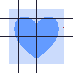
The first thing I want to do is change my coordinate system. Consider: for a 10×10 cell, the center is at the point (5, 5), which neighbors pixels (4, 4) and (5, 5). But that would mean the heart would touch the pixel at (5, 5) immediately, whereas it would need to cross a whole pixel to reach (4, 4), even though both pixels touch the center!
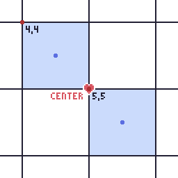
Pixel coordinates refer to the top left corners of the pixels, indicated in red above. The center is a point, not a pixel, and it’s clearly much closer to one pixel coordinate than the other. The fix is to use the centers of pixels, indicated in blue, which are the same distance from where the heart starts. Phew!
(If you don’t do this, you’ll get a very noticeable diagonal gash where the particle touched lower-right pixels earlier than upper-left ones. Guess how I found that out!)
While I’m at it, pixel coordinates are relative to the upper-left corner of the cell, but the most interesting point here is the center. So let’s make them relative to that, too. That means (4, 4) and (5, 5) should really be (-½, -½) and (½, ½), or more generally: given a center at \((c_x, c_y)\), the point I’m actually interested in is \((x + \frac{1}{2} - c_x, y + \frac{1}{2} - c_y)\). Call this, I dunno, \((d_x, d_y)\).
Back to the actual problem, which is: how big does the particle need to grow to hit this point?
Like I said before, I could try scaling the particle up bit by bit (maybe binary search?) until it touches the point, but that still feels goofy and imprecise.
You know, it sucks that the particle is a two-dimensional shape. It would be swell if I could eliminate a dimension here, or something.
And here I borrow a couple techniques from collision detection. Scaling the particle up is equivalent to scaling the entire cell down. If I scaled the cell down towards the origin, the point would trace a straight line.
This is very helpful. It means I can solve this problem with a raycast: fire a straight ray into the particle, towards its center, and check each pixel it hits until I find an opaque one. That’ll give me a perfect answer!
But where does the ray start? I have a point in the grid, but not a point on the particle. So the first question is: if the particle scaled up just enough that the edge of the particle image touched the point, where on the particle would that contact be?
Call the particle dimensions \(p_w\) by \(p_h\). (My heart is contained within a square, but that isn’t strictly necessary.) In order to reach x-coordinate \(d_x\), the particle would have to be twice as wide as the distance from the y-axis to that point — because it’s centered! — which is \(\left|2 d_x\right|\) pixels wide. Its scale, relative to its original size, would thus be \(\frac{\left|2 d_x\right|}{p_w}\). The scale for touching the y-coordinate would be computed the same way. To actually touch the point, the particle has to reach whichever coordinate is further away, so its scale must be:
A special case crops up here: for a cell with an odd width and height, the center pixel is exactly aligned with the origin, and the scale computes to zero. I’m doing some division in a moment, so that’s very bad — but the center pixel is effectively touched immediately, so I can say the final answer for this pixel is 0 and skip the rest of this anyway.
Now for the fun part! When the expanding particle hits the point of interest, it makes contact at some point on the original particle image. If the necessary scale is \(s\), the contact point is the center of the particle, offset by \(\left(\frac{d_x}{s}, \frac{d_y}{s}\right)\).
And now I raycast from that point to the center of the particle and check every pixel that ray crosses, using a modified Bresenham’s algorithm — originally intended for drawing pixel-perfect lines, but perfectly suited for casting a ray through a grid as well. (Conveniently, I’d already implemented this sort of raycast for collision detection for this very same game! Then I ended up not using it, hm.)
When I find an opaque-ish pixel (alpha of 0.5 or greater), I compute its distance from the center, divide by the distance from the contact point to the center — that tells me how much bigger the particle has to grow for the opaque-ish pixel I found to actually touch the point.

Multiply that ratio by the \(s\) I found earlier, and the result is exactly what I was looking for: the scale of the particle when it touches the point!
Now, raycasting for every pixel in the stamp — a thousand times even for a dinky cell size of 32×32 — is not exactly speedy. But it’s not unbearably slow, either. And this is something that’s generated once and played back a bunch of times, so why not spend a little CPU time upfront making it as high-quality as I can manage?
Anyway, that’s the hard part done! Now I can put the mask together.
Phase 2: the mask
With the stamp generated, I also know how big the particle has to grow for the entire cell to be covered: it’s just the highest scale in the stamp. For a simple full-screen effect, all I’d have to do at this point is scale the stamp values into the range [0, 1] and copy them to every cell in the grid.
But that’s boring; I wanted a wipe, which requires a couple more twiddles.
The wipe is essentially a second animation that controls when each cell’s individual animation starts. Above I considered a row-by-row wipe; for Cherry Kisses I ended up with a column-by-column wipe; Cave Story also has an “inwards” wipe. All of these can be generalized as numbered steps in a grid:
1By row      By column   Inwards
277777777    76543210    01233210
366666666    76543210    12344321
455555555    76543210    23455432
544444444    76543210    34566543
633333333    76543210    34566543
722222222    76543210    23455432
811111111    76543210    12344321
900000000    76543210    01233210
The math is basically already done; I did it above. Given the number of steps \(n\) and the delay \(d\) (a fraction of the cell animation time), I can find the length of a cell animation \(t\) as follows:
The process for generating the whole mask is thus:
- Iterate over each pixel of the mask.
- Figure out what cell it’s in, and the step for that cell.
- Find the corresponding value in the stamp, scale it to the size of a cell animation, and add in the delay.
- Write that to the mask.
Once every pixel is done, the mask is complete!
Except… this didn’t handle the overlap issue. No problem, though; that’s surprisingly simple to fix.
First, expand the stamp to the size of a 3×3 block of cells. The maximum scale for a stamp should only be taken from the central cell; the others are for the following process.
Then, when reading a pixel’s stamp in step 3 above, read it from the central cell — and also from the neighboring cells. In those neighbors, I read from the stamp cell on the opposite side, in order to know how long it would take for the heart to grow out of that cell and into this one.

(Diagonal neighbors aren’t shown here, but you get the idea.)
Since different cells may have different start times, I may need to add/subtract some extra delay from the neighbors’ values. Then I take the smallest of all these samples to figure out the earliest time that any heart — either in this cell, or one of its neighbors — hits the pixel.
And hey, presto, we’re done! Here’s a (somewhat laggy) recording I took of the very first time I got this working for Cherry Kisses:

It ended up a little nicer-looking than that, of course. (Feel free to play the game to see it in action?) And if you’re curious, here’s the mask from the final game:

Caveats
There’s one teeny tiny problem still lingering in this approach. I assume that the whole animation ends when the last cell animation ends, but because of cell overlap, it might actually end earlier. And indeed, when I went back to check the Cherry Kisses mask, I found that it ends early — the brightest color in it is #e2e2e2. Oops. So much for that ludicrous accuracy!
That’s still fixable by taking overlap into account when finding the maximum value in the stamp, but I haven’t done it yet, and it’s a bit more complicated if the grid pattern has adjacent cells that are more than 1 step apart. (Those cases can also lead to particles mashing against the cell edge too early, which could be fixed by using a 5×5 or larger stamp…)
That's it
Yep. The particle generator is just this logic with some knobs bolted on. It has a couple extra features, like a “halo” that highlights the transition point, and using all three color channels for extra precision, but it’s all built on the same basic idea.
There’s a lot of room for experimentation and variety here, and I’ve probably only scratched the surface. This is only a tiny subset of what can be done with a transition mask, too — it needn’t rely on a grid at all! See what you can come up with.
Oh, and here’s the exact shader I used in Cherry Kisses. It’s for LÖVE, so it has a couple non-standard #defines and globals, but you get the idea. The “ramp” is just a tolerance that adds a soft edge around the transition.
 1extern Image mask;
 2extern float t;
 3extern float ramp;
 4
 5vec4 effect(vec4 color, Image texture, vec2 tex_coords, vec2 screen_coords) {
 6    vec4 pixel = Texel(texture, tex_coords) * color;
 7    float discriminator = Texel(mask, screen_coords / love_ScreenSize.xy).r;
 8    float alpha = clamp((t - discriminator) / ramp + 0.5, 0.0, 1.0);
 9    pixel.a *= alpha;
10    return pixel;
11}
Happy transitioning!