
 notepad
![[process]](https://eev.ee/theme/images/category-process.png)
This is a series about Star Anise Chronicles: Cheezball Rising, an expansive adventure game about my cat for the Game Boy Color. Follow along as I struggle to make something with this bleeding-edge console!
GitHub has intermittent prebuilt ROMs, or you can get them a week early on Patreon if you pledge $4. More details in the README!
In this issue, I figure out how to put literally anything on the goddamn screen, then add a splash of color.
Next: drawing a sprite.
The plan
I’m making a Game Boy Color game!
I have no— okay, not much idea what I’m doing, so I’m going to document my progress as I try to forge a 90s handheld game out of nothing.
I do usually try to keep tech stuff accessible, but this is going to get so arcane that that might be a fool’s errand. Think of this as less of an extended tutorial, more of a long-form Twitter.
Also, I’ll be posting regular builds on Patreon for $4 supporters, which will be available a week later for everyone else. I imagine they’ll generally stay in lockstep with the posts, unless I fall behind on the writing part. But when has that ever happened?
Your very own gamedev legend is about to unfold! A world of dreams and adventures with gbz80 assembly awaits! Let’s go!
Prerequisites
First things first. I have a teeny bit of experience with Game Boy hacking, so I know I need:
-
An emulator. I have no way to run arbitrary code on an actual Game Boy Color, after all. I like mGBA, which strives for accuracy and has some debug tools built in.
There’s already a serious pitfall here: emulators are generally designed to run games that would work correctly on the actual hardware, but they won’t necessarily reject games that wouldn’t work on actual hardware. In other words, something that works in an emulator might still not work on a real GBC. I would of course prefer that this game work on the actual console it’s built for, but I’ll worry about that later.
-
An assembler, which can build Game Boy assembly code into a ROM. I pretty much wrote one of these myself already for the Pokémon shenanigans, but let’s go with something a little more robust here. I’m using RGBDS, which has a couple nice features like macros and a separate linking step. It compiles super easily, too.
I also hunted down a vim syntax file, uh, somewhere. I can’t remember which one it was now, and it’s kind of glitchy anyway.
-
Some documentation. I don’t know exactly how this surfaced, but the actual official Game Boy programming manual is on archive.org. It glosses over some things and assumes some existing low-level knowledge, but for the most part it’s a very solid reference.
For everything else, there’s Google, and also the curated awesome-gbdev list of resources.
That list includes several skeleton projects for getting started, but I’m not going to use them. I want to be able to account for every byte of whatever I create. I will, however, refer to them if I get stuck early on. (Spoilers: I get stuck early on.)
And that’s it! The rest is up to me.
Making nothing from nothing
Might as well start with a Makefile. The rgbds root documentation leads me to the following incantation:
1all:
2        rgbasm -o main.o main.rgbasm
3        rgblink -o gamegirl.gb main.o
4        rgbfix -v -p 0 gamegirl.gb
(I, uh, named this project “gamegirl” before I figured out what it was going to be. It’s a sort of witticism, you see.)
This works basically like every C compiler under the sun, as you might expect: every source file compiles to an object file, then a linker bundles all the object files into a ROM. If I only change one source file, I only have to rebuild one object file.
Of course, this Makefile is terrible garbage and will rebuild the entire project unconditionally every time, but at the moment that takes a fraction of a second so I don’t care.
The extra rgbfix step is new, though — it adds the Nintendo logo (the one you see when you start up a Game Boy) to the header at the beginning of the ROM. Without this, the console will assume the cartridge is dirty or missing or otherwise unreadable, and will refuse to do anything at all. (I could also bake the logo into the source itself, but given that it’s just a fixed block of bytes and rgbfix is bundled with the assembler, I see no reason to bother with that.)
All I need now is a source file, main.rgbasm, which I populate with:
1
Nothing! I don’t know what I expect from this, but I’m curious to see what comes out. And what comes out is a working ROM!

Maybe “working” is a strong choice of word, given that it doesn’t actually do anything.
Doing something
It would be fantastic to put something on the screen. This turned out to be harder than expected.
First attempt. I know that the Game Boy starts running code at $0150, immediately after the end of the header. So I’ll put some code there.
A brief Game Boy graphics primer: there are two layers, the background and objects. (There’s also a third layer, the window, which I don’t entirely understand yet.) The background is a grid of 8×8 tiles, two bits per pixel, for a total of four shades of gray. Objects can move around freely, but they lose color 0 to transparency, so they can only use three colors.
There are lots more interesting details and restrictions, which I will think about more later.
Drawing objects is complicated, and all I want to do right now is get something. I’m pretty sure the background defaults to showing all tile 0, so I’ll try replacing tile 0 with a gradient and see what happens.
Tiles are 8×8 and two bits per pixel, which means each row takes two bytes, and the whole tile is 16 bytes. Tiles are defined in one big contiguous block starting at $8000 — or, maybe $8800, sometimes — so all I need to do is:
 1SECTION "main", ROM0[$0150]
 2    ld hl, $8000
 3    ld a, %00011011
 4    REPT 16
 5    ld [hl+], a
 6    ENDR
 7
 8_halt:
 9    ; Do nothing, forever
10    halt
11    nop
12    jr _halt
If you are not familiar with assembly, this series is going to be a wild ride. But here’s a very very brief primer.
Assembly language — really, an assembly language — is little more than a set of human-readable names for the primitive operations a CPU knows how to do. And those operations, by and large, consist of moving bytes around. The names tend to be very short, because you end up typing them a lot.
Most of the work is done in registers, which are a handful of spaces for storing bytes right on the CPU. At this level, RAM is relatively slow — it’s further away, outside the chip — so you want to do as much work as possible in registers. Indeed, most operations can only be done on registers, so there’s a lot of fetching stuff from RAM and operating on it and then putting it back in RAM.
The Game Boy CPU, a modified Z80, has eight byte-sized registers. They’re often referred to in pairs, because they can be paired up to make a 16-bit values (giving you access to a full 64KB address space). And they are: af, bc, de, hl.
The af pair is special. The f register is used for flags, such as whether the last instruction caused an overflow, so it’s not generally touched directly. The a register is called the accumulator and is most commonly used for math operations — in fact, a lot of math operations can only be done on a. The hl register is most often used for addresses, and there are a couple instructions specific to hl that are convenient for memory access. (The h and l even refer to the high and low byte of an address.) The other two pairs aren’t especially noteworthy.
Also! Not every address is actually RAM; the address space ($0000 through $ffff) is carved into several distinct areas, which we will see as I go along. $8000 is the beginning of display RAM, which the screen reads from asynchronously. Also, a lot of addresses above $ff00 (also called “registers”) are special and control hardware in some way, or even perform some action when written to.
With that in mind, here’s the above code with explanatory comments:
 1; This is a directive for the assembler to put the following
 2; code at $0150 in the final ROM.
 3SECTION "main", ROM0[$0150]
 4    ; Put the hex value $8000 into registers hl.  Really, that
 5    ; means put $80 into h and $00 into l.
 6    ld hl, $8000
 7
 8    ; Put this binary value into registers a.
 9    ; It's just 0 1 2 3, a color gradient.
10    ld a, %00011011
11
12    ; This is actually a macro this particular assembler
13    ; understands, which will repeat the following code 16
14    ; times, exactly as if I'd copy-pasted it.
15    REPT 16
16
17    ; The brackets (sometimes written as parens) mean to use hl
18    ; as a position in RAM, rather than operating on hl itself.
19    ; So this copies a into the position in RAM given by
20    ; hl (initially $8000), and the + adds 1 to hl afterwards.
21    ; This is one reason hl is nice for storing addresses: the +
22    ; variant is handy for writing a sequence of bytes to RAM,
23    ; and it only exists for hl.
24    ld [hl+], a
25
26    ; End the REPT block
27    ENDR
28
29; This is a label, used to refer to some position in the code.
30; It only exists in the source file.
31_halt:
32    ; Stop all CPU activity until there's an interrupt.  I
33    ; haven't turned any interrupts on, so this stops forever.
34    halt
35
36    ; The Game Boy hardware has a bug where, under rare and
37    ; unspecified conditions, the instruction after a halt will
38    ; be skipped.  So every halt should be followed by a nop,
39    ; "no operation", which does nothing.
40    nop
41
42    ; This jumps back up to the label.  It's short for "jump
43    ; relative", and will end up as an instruction saying
44    ; something like "jump backwards five bytes", or however far
45    ; back _halt is.  (Different instructions can be different
46    ; lengths.)
47    jr _halt
Okay! Glad you’re all caught up. The rgbds documentation includes a list of all the available operations (as well as assembler syntax), and once you get used to the short names, I also like this very compact chart of all the instructions and how they compile to machine code. (Note that that chart spells [hl+] as (HLI), for “increment” — the human-readable names are somewhat arbitrary and can sometimes vary between assemblers.)
Now, let’s see what this does!
Wow! It’s… still nothing. Hang on.
If I open the debugger and hit Break, I find out that the CPU is at address $0120 — before my code — and is on an instruction DD. What’s DD? Well, according to this convenient chart, it’s… nothing. That’s not an instruction.
Hmm.
Problem solving
Maybe it’s time to look at one of those skeleton projects after all. I crack open the smallest one, gb-template, and it seems to be doing the same thing: its code starts at $0150.
It takes me a bit to realize my mistake here. Practically every Game Boy game starts its code at $0150, but that’s not what the actual hardware specifies. The real start point is $0100, which is immediately before the header! There are only four bytes before the header, just enough for… a jump instruction.
Okay! No problem.
1SECTION "entry point", ROM0[$0100]
2    nop
3    jp $0150
Why the nop? I have no idea, but all of these boilerplate projects do it.
Uhh.
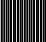
Well, that’s weird. Not only is the result black and white when I definitely used all four shades, but the whites aren’t even next to each other. (I also had a strange effect where the screen reverted to all white after a few seconds, but can’t reproduce it now; it was fixed by the same steps, though, so it may have been a quirk of a particular mGBA build.)
I’ll save you my head-scratching. I made two mistakes here. Arguably, three!
First: believe it or not, I have to specify the palette. Even in original uncolored Game Boy mode! I can see how that’s nice for doing simple fade effects or flashing colors, but I didn’t suspect it would be necessary. The monochrome palette lives at $ff47 (one of those special high addresses), so I do this before anything else:
1    ld a, %11100100         ; 3 2 1 0
2    ld [$ff47], a
I should really give names to some of these special addresses, but for now I’m more interested in something that works than something that’s nice to read.
Second: I specified the colors wrong. I assumed that eight pixels would fit into two bytes as AaBbCcDd EeFfGgHh, perhaps with some rearrangement, but a closer look at Nintendo’s manual reveals that they need to be ABCDEFGH abcdefgh, with the two bits for each pixel split across each byte! Wild.
Handily, rgbds has syntax for writing out pixel values directly: a backtick followed by eight of 0, 1, 2, and 3. I just have to change my code a bit to write two bytes, eight times each. By putting a 16-bit value in a register pair like bc, I can read its high and low bytes out individually via the b and c registers.
1    ld hl, $8000
2    ld bc, `00112233
3    REPT 8
4    ld a, b
5    ld [hl+], a
6    ld a, c
7    ld [hl+], a
8    ENDR
Third: strictly speaking, I don’t think I should be writing to $8000 while the screen is on, because the screen may be trying to read from it at the same time. It does happen to work in this emulator, but I have no idea whether it would work on actual hardware. I’m not going to worry too much about this test code; most likely, tile loading will happen all in one place in the real game, and I can figure out any issues then.
This is one of those places where the manual is oddly vague. It dedicates two whole pages to diagrams of how sprites are drawn when they overlap, yet when I can write to display RAM is left implicit.
Well, whatever. It works on my machine.
Success! I made a thing for the Game Boy.
Ah, but what I wanted was a thing for the Game Boy Color. That shouldn’t be too much harder.
Now in Technicolor
First I update my Makefile to pass the -C flag to rgbfix. That tells it to set a flag in the ROM header to indicate that this game is only intended for the Game Boy Color, and won’t work on the original Game Boy. (In order to pass Nintendo certification, I’ll need an error screen when the game is run on a non-Color Game Boy, but that can come later. Also, I don’t actually know how to do that.)
Oh, and I’ll change the file extension from .gb to .gbc. And while I’m in here, I might as well repeat myself slightly less in this bad, bad Makefile.
1TARGET := gamegirl.gbc
2
3all: $(TARGET)
4
5$(TARGET):
6        rgbasm -o main.o main.rgbasm
7        rgblink -o $(TARGET) main.o
8        rgbfix -C -v -p 0 $(TARGET)
I think := is the one I want, right? Christ, who can remember how this syntax works.
Next I need to define a palette. Again, everything defaults to palette zero, so I’ll update that and not have to worry about specifying a palette for every tile.
This part is a bit weird. Unlike tiles, there’s not a block of addresses somewhere that contains all the palettes. Instead, I have to write the palette to a single address one byte at a time, and the CPU will put it… um… somewhere.
(I think this is because the entire address space was already carved up for the original Game Boy, and they just didn’t have room to expose palettes, but they still had a few spare high addresses they could use for new registers.)
Two registers are involved here. The first, $ff68, specifies which palette I’m writing to. It has a bunch of parts, but since I’m writing to the first color of palette zero, I can leave it all zeroes. The one exception is the high bit, which I’ll explain in just a moment.
1    ld a, %10000000
2    ld [$ff68], a
The other, $ff69, does the actual writing. Each color in a palette is two bytes, and a palette contains four colors, so I need to write eight bytes to this same address. The high bit in $ff68 is helpful here: it means that every time I write to $ff69, it should increment its internal position by one. This is kind of like the [hl+] I used above: after every write, the address increases, so I can just write all the data in sequence.
But first I need some colors! Game Boy Color colors are RGB555, which means each color is five bits (0–31) and a full color fits in two bytes: 0bbbbbgg gggrrrrr.
(I got this backwards initially and thought the left bits were red and the right bits were blue.)
Thus, I present, palette loading by hand. Like before, I put the 16-bit color in bc and then write out the contents of b and c. (Before, the backtick syntax put the bytes in the right order; colors are little-endian, hence why I write c before b.)
 1    ld bc, %0111110000000000  ; blue
 2    ld a, c
 3    ld [$ff69], a
 4    ld a, b
 5    ld [$ff69], a
 6    ld bc, %0000001111100000  ; green
 7    ld a, c
 8    ld [$ff69], a
 9    ld a, b
10    ld [$ff69], a
11    ld bc, %0000000000011111  ; red
12    ld a, c
13    ld [$ff69], a
14    ld a, b
15    ld [$ff69], a
16    ld bc, %0111111111111111  ; white
17    ld a, c
18    ld [$ff69], a
19    ld a, b
20    ld [$ff69], a
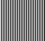
Rebuild, and:

What a glorious eyesore!
To be continued
That brings us up to commit 212344 and works as a good stopping point.
Next time: drawing a sprite!