
 notepad
![[process]](https://eev.ee/theme/images/category-process.png)
This is a series about Star Anise Chronicles: Cheezball Rising, an expansive adventure game about my cat for the Game Boy Color. Follow along as I struggle to make something with this bleeding-edge console!
GitHub has intermittent prebuilt ROMs, or you can get them a week early on Patreon if you pledge $4. More details in the README!
In this issue, I fill in the remaining bits necessary to have something that looks like a game.
Previously: drawing a sprite.
Next: a little spring cleaning.
Recap
So far, I have this.

It took unfathomable amounts of effort, but it’s something! Now to improve this from a static image to something a bit more game-like.
Quick note: I’ve been advised to use the de facto standard hardware.inc file, which gives symbolic names to all the registers and some of the flags they use. I hadn’t introduced it yet while doing the work described in this post, but for the sake of readability, I’m going to pretend I did and use that file’s constants in the code snippets here.
Interrupts
To get much further, I need to deal with interrupts. And to explain interrupts, I need to briefly explain calls.
Assembly doesn’t really have functions, only addresses and jumps. That said, the Game Boy does have call and ret instructions. A call will push the PC register (program counter, the address of the current instruction) onto the stack and perform a jump; a ret will pop into the PC register, effectively jumping back to the source of the call.
There are no arguments, return values, or scoping; input and output must be mediated by each function, usually via registers. Of course, since registers are global, a “function” might trample over their values in the course of whatever work it does. A function can manually push and pop 16-bit register pairs to preserve their values, or leave it up to the caller for speed/space reasons. All the conventions are free for me to invent or ignore. A “function” can even jump directly to another function and piggyback on the second function’s ret, kind of like Perl’s goto &sub… which I realize is probably less common knowledge than how call/return work in assembly.
Interrupts, then, are calls that can happen at any time. When one of a handful of conditions occurs, the CPU can immediately (or, rather, just before the next instruction) call an interrupt handler, regardless of what it was already doing. When the handler returns, execution resumes in the interrupted code.
Of course, since they might be called anywhere, interrupt handlers need to be very careful about preserving the CPU state. Pushing af is especially important (and this is the one place where af is used as a pair), because a is necessary for getting almost anything done, and f holds the flags which most instructions will invisibly trample.
Naturally, I completely forgot about this the first time around.
The Game Boy has five interrupts, each with a handler at a fixed address very low in ROM. Each handler only has room for eight bytes’ worth of instructions, which is enough to do a very tiny amount of work — or to just jump elsewhere.
A good start is to populate each one with only the reti instruction, which returns as usual and re-enables interrupts. The CPU disables interrupts when it calls an interrupt handler (so they thankfully can’t interrupt themselves), and returning with only ret will leave them disabled.
Naturally, I completely forgot about this the first time around.
 1; Interrupt handlers
 2SECTION "Vblank interrupt", ROM0[$0040]
 3    ; Fires when the screen finishes drawing the last physical
 4    ; row of pixels
 5    reti
 6
 7SECTION "LCD controller status interrupt", ROM0[$0048]
 8    ; Fires on a handful of selectable LCD conditions, e.g.
 9    ; after repainting a specific row on the screen
10    reti
11
12SECTION "Timer overflow interrupt", ROM0[$0050]
13    ; Fires at a configurable fixed interval
14    reti
15
16SECTION "Serial transfer completion interrupt", ROM0[$0058]
17    ; Fires when the serial cable is done?
18    reti
19
20SECTION "P10-P13 signal low edge interrupt", ROM0[$0060]
21    ; Fires when a button is released?
22    reti
These will do nothing. I mean, obviously, but they’ll do even less than nothing until I enable them. Interrupts are enabled by the dedicated ei instruction, which enables any interrupts whose corresponding bit is set in the IE register ($ffff).
So… which one do I want?
Game loop
To have a game, I need a game loop. The basic structure of pretty much any loop looks like:
- Load stuff.
- Check for input.
- Update the game state.
- Draw the game state.
- GOTO 2
(If you’ve never seen a real game loop written out before, LÖVE’s default loop is a good example, though even a huge system like Unity follows the same basic structure.)
The Game Boy seems to introduce a wrinkle here. I don’t actually draw anything myself; rather, the hardware does the drawing, and I tell it what to draw by using the palette registers, OAM, and VRAM.
But in fact, this isn’t too far off from how LÖVE (or Unity) works! All the drawing I do is applied to a buffer, not the screen; once the drawing is complete, the main loop calls present(), which waits until vblank and then draws the buffer to the screen. So what you see on the screen is delayed by up to a frame, and the loop really has an extra “wait for vsync” step at 3½. Or, with a little rearrangement:
- Load stuff.
- Wait for vblank.
- Draw the game state.
- Check for input.
- Update the game state.
- GOTO 2
This is approaching something I can implement! It works out especially well because it does all the drawing as early as possible during vblank. That’s good, because the LCD operation looks something like this:
1LCD redrawing...
2LCD redrawing...
3LCD redrawing...
4LCD redrawing...
5VBLANK
6LCD idle
7LCD idle
While the LCD is refreshing, I can’t (easily) update anything it might read from. I only have free control over VRAM et al. during a short interval after vblank, so I need to do all my drawing work right then to ensure it happens before the LCD starts refreshing again. Then I’m free to update the world while the LCD is busy.
First, right at the entry point, I enable the vblank interrupt. It’s bit 0 of the IE register, but hardware.inc has me covered.
1main:
2    ; Enable interrupts
3    ld a, IEF_VBLANK
4    ldh [rIE], a
5    ei
Next I need to make the handler actually do something. The obvious approach is for the handler to call one iteration of the game loop, but there are a couple problems with that. For one, interrupts are disabled when a handler is called, so I would never get any other interrupts. I could explicitly re-enable interrupts, but that raises a bigger question: what happens if the game lags, and updating the world takes longer than a frame? With this approach, the game loop would interrupt itself and then either return back into itself somewhere and cause untold chaos, or take too long again and eventually overflow the stack. Neither is appealing.
An alternative approach, which I found in gb-template but only truly appreciated after some thought, is for the vblank handler to set a flag and immediately return. The game loop can then wait until the flag is set before each iteration, just like LÖVE does. If an update takes longer than a frame, no problem: the loop will always wait until the next vblank, and the game will simply run more slowly.
 1SECTION "Vblank interrupt", ROM0[$0040]
 2    push hl
 3    ld hl, vblank_flag
 4    ld [hl], 1
 5    pop hl
 6    reti
 7
 8...
 9
10SECTION "Important twiddles", WRAM0[$C000]
11; Reserve a byte in working RAM to use as the vblank flag
12vblank_flag:
13    db
The handler fits in eight bytes — the linker would yell at me if it didn’t, since another section starts at $0048! — and leaves all the registers in their previous states. As I mentioned before, I originally neglected to preserve registers, and some zany things started to happen as a and f were abruptly altered in the middle of other code. Whoops!
Now the main loop can look like this:
 1main:
 2    ; ... bunch of setup code ...
 3
 4vblank_loop:
 5    ; Main loop: halt, wait for a vblank, then do stuff
 6
 7    ; The halt instruction stops all CPU activity until the
 8    ; next interrupt, which saves on battery, or at least on
 9    ; CPU cycles on an emulator's host system.
10    halt
11    ; The Game Boy has some obscure hardware bug where the
12    ; instruction after a halt is occasionally skipped over,
13    ; so every halt should be followed by a nop.  This is so
14    ; ubiquitous that rgbasm automatically adds a nop after
15    ; every halt, so I don't even really need this here!
16    nop
17
18    ; Check to see whether that was a vblank interrupt (since
19    ; I might later use one of the other interrupts, all of
20    ; which would also cancel the halt).
21    ld a, [vblank_flag]
22    ; This sets the zero flag iff a is zero
23    and a
24    jr z, vblank_loop
25    ; This always sets a to zero, and is shorter (and thus
26    ; faster) than ld a, 0
27    xor a, a
28    ld [vblank_flag], a
29
30    ; Use DMA to update object attribute memory.
31    ; Do this FIRST to ensure that it happens before the screen starts to update again.
32    call $FF80
33
34    ; ... update everything ...
35
36    jp vblank_loop
It’s looking all the more convenient that I have my own copy of OAM — I can update it whenever I want during this loop! I might need similar facilities later on for editing VRAM or changing palettes.
Doing something and reading input
I have a loop, but since nothing’s happening, that’s not especially obvious. Input would take a little effort, so I’ll try something simpler first: making Anise move around.
I don’t actually track Anise’s position anywhere right now, except for in the OAM buffer. Good enough. In my main loop, I add:
1    ld hl, oam_buffer + 1
2    ld a, [hl]
3    inc a
4    ld [hl], a
The second byte in each OAM entry is the x-coordinate, and indeed, this causes Anise’s torso to glide rightwards across the screen at 60ish pixels per second. Eventually the x-coordinate overflows, but that’s fine; it wraps back to zero and moves the sprite back on-screen from the left.

Excellent. I mean, sorry, this is extremely hard to look at, but bear with me a second.
This would be a bit more game-like if I could control it with the buttons, so let’s read from them.
There are eight buttons: up, down, left, right, A, B, start, select. There are also eight bits in a byte. You might suspect that I can simply read an I/O register to get the current state of all eight buttons at once.
Ha, ha! You naïve fool. Of course it’s more convoluted than that. That single byte thing is a pretty good idea, though, so what I’ll do is read the input at the start of the frame and coax it into a byte that I can consult more easily later.
Turns out I pretty much have to do that, because button access is slightly flaky. Even the official manual advises reading the buttons several times to get a reliable result. Yikes.
Here’s how to do it. The buttons are wired in two groups of four: the dpad and everything else. Reading them is thus also done in two groups of four. I need to use the P1 register, which I assume is short for “player 1” and is so named because the people who designed this hardware had also designed the two-player NES?
Bits 5 and 6 of P1 determine which set of four buttons I want to read, and then the lower nybble contains the state of those buttons. Note that each bit is set to 1 if the button is released; I think this is a quirk of how they’re wired, and what I’m doing is extremely direct hardware access. Exciting! (Also very confusing on my first try, where Anise’s movement was inverted.)
The code, which is very similar to an example in the official manual, thus looks like this:
 1    ; Poll input
 2    ; It takes a moment to get a reliable read after requesting
 3    ; a particular set of buttons, so we need to wait a moment;
 4    ; this is based on the code from the manual, which stalls
 5    ; simply by reading multiple times
 6
 7    ; Bit 5 means to read the dpad
 8    ; (Well, Actually: bit 4 being OFF means to read the d-pad)
 9    ld a, $20
10    ldh [rP1], a
11    ; But it's unreliable, so do it twice
12    ld a, [rP1]
13    ld a, [rP1]
14    ; This is 'complement', and flips all the bits in a, so now
15    ; set bits will mean a button is held down
16    cpl
17    ; Store the lower four bits in b
18    and a, $0f
19    ld b, a
20
21    ; Bit 4 means to read the buttons
22    ; (Same caveat; it's really that bit 5 is off)
23    ld a, $10
24    ldh [rP1], a
25    ; Not sure why this needs more stalling?  Someone speculated
26    ; that this circuitry might just be further away
27    ld a, [rP1]
28    ld a, [rP1]
29    ld a, [rP1]
30    ld a, [rP1]
31    ld a, [rP1]
32    ld a, [rP1]
33    ; Again, complement and mask off the lower four bits
34    cpl
35    and a, $0f
36    ; b already contains four bits, so I need to shift something
37    ; left by four...  but the shift instructions only go one
38    ; bit at a time, ugh!  Luckily there's swap, which swaps the
39    ; high and low nybbles in any register
40    swap a
41    ; Combine b's lower nybble with a's high nybble
42    or a, b
43    ; And finally store it in RAM
44    ld [buttons], a
45
46...
47
48SECTION "Important twiddles", WRAM0[$C000]
49vblank_flag:
50    db
51buttons:
52    db
Phew. That was a bit of a journey, but now I have the button state as a single byte. To help with reading the buttons, I’ll also define a few constants labeling the individual bits. (There are instructions for reading a particular bit by number, so I don’t need to mask a single bit out.)
1; Constants
2BUTTON_RIGHT  EQU 0
3BUTTON_LEFT   EQU 1
4BUTTON_UP     EQU 2
5BUTTON_DOWN   EQU 3
6BUTTON_A      EQU 4
7BUTTON_B      EQU 5
8BUTTON_START  EQU 6
9BUTTON_SELECT EQU 7
Now to adjust the sprite position based on what directions are held down. Delete the old code and replace it with:
 1    ; Set b/c to the y/x coordinates
 2    ld hl, oam_buffer
 3    ld b, [hl]
 4    inc hl
 5    ld c, [hl]
 6
 7    ; This sets the z flag to match a particular bit in a
 8    bit BUTTON_LEFT, a
 9    ; If z, the bit is zero, so left isn't held down
10    jr z, .skip_left
11    ; Otherwise, left is held down, so decrement x
12    dec c
13.skip_left:
14
15    ; The other three directions work the same way
16    bit BUTTON_RIGHT, a
17    jr z, .skip_right
18    inc c
19.skip_right:
20    bit BUTTON_UP, a
21    jr z, .skip_up
22    dec b
23.skip_up:
24    bit BUTTON_DOWN, a
25    jr z, .skip_down
26    inc b
27.skip_down:
28
29    ; Finally, write the new coordinates back to the OAM
30    ; buffer, which hl is still pointing into
31    ld [hl], c
32    dec hl
33    ld [hl], b
Miraculously, Anise’s torso now moves around on command!

Neat! But this still looks really, really, incredibly bad.
Aesthetics
It’s time to do something about this artwork.
First things first: I’m really tired of writing out colors by hand, in binary, so let’s fix that. In reality, I did this bit after adding better art, but doing it first is better for everyone.
I think I’ve mentioned before that rgbasm has (very, very rudimentary) support for macros, and this seems like a perfect use case for one. I’d like to be able to write colors out in typical rrggbb hex fashion, so I need to convert a 24-bit color to a 16-bit one.
1dcolor: MACRO  ; $rrggbb -> gbc representation
2_r = ((\1) & $ff0000) >> 16 >> 3
3_g = ((\1) & $00ff00) >> 8  >> 3
4_b = ((\1) & $0000ff) >> 0  >> 3
5    dw (_r << 0) | (_g << 5) | (_b << 10)
6    ENDM
This is going to need a whole paragraph of caveats.
A macro is contained between MACRO and ENDM. The assembler has a curious sort of universal assignment syntax, where even ephemeral constructs like macros are introduced by labels. Macros can take arguments, but they aren’t declared; they’re passed more like arguments to shell scripts, where the first argument is \1 and so forth. (There’s even a SHIFT command for accessing arguments beyond the ninth.) Also, passing strings to a macro is some kind of byzantine nightmare where you have to slap backslashes in just the right places and I will probably avoid doing it altogether if I can at all help it.
Oh, one other caveat: compile-time assignments like I have above must start in the first column. I believe this is because assignments are also labels, and labels have to start in the first column. It’s a bit weird and apparently rgbasm’s lexer is horrifying, but I’ll take it over writing my own assembler and stretching this project out any further.
Anyway, all of that lets me write dcolor $ff0044 somewhere and have it translated at compile time to the appropriate 16-bit value. (I used dcolor to parallel db and friends, but I’m strongly considering using CamelCase exclusively for macros? Guess it depends how heavily I use them.)
With that on hand, I can now doodle some little sprites in Aseprite and copy them in. This part is not especially interesting and involves a lot of squinting at zoomed-in sprites.
 1SECTION "Sprites", ROM0
 2PALETTE_BG0:
 3    dcolor $80c870  ; light green
 4    dcolor $48b038  ; darker green
 5    dcolor $000000  ; unused
 6    dcolor $000000  ; unused
 7PALETTE_ANISE:
 8    dcolor $000000  ; TODO
 9    dcolor $204048
10    dcolor $20b0b0
11    dcolor $f8f8f8
12GRASS_SPRITE:
13    dw `00000000
14    dw `00000000
15    dw `01000100
16    dw `01010100
17    dw `00010000
18    dw `00000000
19    dw `00000000
20    dw `00000000
21EMPTY_SPRITE:
22    dw `00000000
23    dw `00000000
24    dw `00000000
25    dw `00000000
26    dw `00000000
27    dw `00000000
28    dw `00000000
29    dw `00000000
30ANISE_SPRITE:
31    ; ... I'll revisit this momentarily
Gorgeous. You may notice that I put the colors as data instead of inlining them in code, which incidentally makes the code for setting the palette vastly shorter as well:
 1    ; Start setting the first color, and advance the internal
 2    ; pointer on every write
 3    ld a, %10000000
 4    ; BCPS = Background Color Palette Specification
 5    ldh [rBCPS], a
 6
 7    ld hl, PALETTE_BG0
 8    REPT 8
 9    ld a, [hl+]
10    ; Same, but Data
11    ld [rBCPD], a
12    ENDR
Loading sprites into VRAM also becomes a bit less of a mess:
 1    ; Load some basic tiles
 2    ld hl, $8000
 3
 4    ; Read the 16-byte empty sprite into tile 0
 5    ld bc, EMPTY_SPRITE
 6    REPT 16
 7    ld a, [bc]
 8    inc bc
 9    ld [hl+], a
10    ENDR
11
12    ; Read the grass sprite into tile 1, which immediately
13    ; follows tile 0, so hl is already in the right place
14    ld bc, GRASS_SPRITE
15    REPT 16
16    ld a, [bc]
17    inc bc
18    ld [hl+], a
19    ENDR
Someday I should write an actual copy function, since at the moment, I’m using an alarming amount of space for pointlessly unrolled loops. Maybe later.
You may notice I now have two tiles, whereas before I was relying on filling the entire screen with one tile, tile 0. I want to dot the landscape with tile 1, which means writing a bit more to the actual background grid, which begins at $9800 and has one byte per tile.
 1    ; Fill the screen buffer with a pattern of grass tiles,
 2    ; where every 2x2 block has a single grass at the top left.
 3    ; Note that the buffer is 32x32 tiles, and it ends at $9c00
 4    ld hl, $9800
 5.screen_fill_loop:
 6    ; Use tile 1 for every other tile in this row.  Note that
 7    ; REPTed part increments hl /twice/, thus skipping a tile
 8    ld a, $01
 9    REPT 16
10    ld [hl+], a
11    inc hl
12    ENDR
13    ; Skip an entire row of 32 tiles, which will remain empty.
14    ; There is almost certainly a better way to do this, but I
15    ; didn't do it.  (Hint: it's ld bc, $20; add hl, bc)
16    REPT 32
17    inc hl
18    ENDR
19    ; If we haven't reached $9c00 yet, continue looping
20    ld a, h
21    cp a, $9C
22    jr c, .screen_fill_loop
Sorry for all these big blocks of code, but check out this payoff!
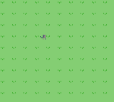
POW! Gorgeous.
And hey, why stop there? With a little more pixel arting against a very reduced palette…
 1SPRITE_ANISE_FRONT_1:
 2    dw `00000111
 3    dw `00001222
 4    dw `00012222
 5    dw `00121222
 6    dw `00121122
 7    dw `00121111
 8    dw `00121122
 9    dw `00121312
10    dw `00121313
11    dw `00012132
12    dw `00001211
13    dw `00000123
14    dw `00100123
15    dw `00011133
16    dw `00000131
17    dw `00000010
18SPRITE_ANISE_FRONT_2:
19    dw `11100000
20    dw `22210000
21    dw `22221000
22    dw `22212100
23    dw `22112100
24    dw `11112100
25    dw `22112100
26    dw `21312100
27    dw `31312100
28    dw `23121000
29    dw `11210000
30    dw `32100000
31    dw `32100000
32    dw `33100000
33    dw `13100000
34    dw `01000000
Yes, I am having trouble deciding on a naming convention.
This is now a 16×16 sprite, made out of two 8×16 parts. This post has enough code blocks as it is, and the changes to make this work are relatively minor copy/paste work, so the quick version is:
- Set the LCDC flag (bit 2, or
LCDCF_OBJ16) that makes objects be 8×16. This mode uses pairs of tiles, so an object that uses either tile 0 or 1 will draw both of them, with tile 0 on top of tile 1. - Extend the code that loads object tiles to load four instead.
- Define a second sprite that’s 8 pixels to the right of the first one.
- Remove the hard-coded object palette, and instead load the
PALETTE_ANISEthat I sneakily included above. This time the registers are calledrOCPSandrOCPD.
Finally, extend the code that moves the sprite to also move the second half:
 1    ; Finally, write the new coordinates back to the OAM
 2    ; buffer, which hl is still pointing into
 3    ld [hl], c
 4    dec hl
 5    ld [hl], b
 6    ; This bit is new: copy the x-coord into a so I can add 8
 7    ; to it, then store both coords into the second sprite's
 8    ; OAM data
 9    ld a, c
10    add a, 8
11    ; I could've written this the other way around, but I did
12    ; not, I guess because this structure mirrors the above?
13    ld hl, oam_buffer + 5
14    ld [hl], a
15    dec hl
16    ld [hl], b
Cross my fingers, and…

Hey hey hey! That finally looks like something!
To be continued
It was a surprisingly long journey, but this brings us more or less up to commit 313a3e, which happens to be the first commit I made a release of! It’s been more than a week, so you can grab it on Patreon or GitHub. I strongly recommend playing it with a release of mGBA prior to 0.7, for… reasons that will become clear next time.
Next time: I’ll take a breather and clean up a few things.