This is a series about Star Anise Chronicles: Cheezball Rising, an expansive adventure game about my cat for the Game Boy Color. Follow along as I struggle to make something with this bleeding-edge console!
GitHub has intermittent prebuilt ROMs, or you can get them a week early on Patreon if you pledge $4. More details in the README!
In this issue, I bash my head against a rock. Sorry, I mean I bash Star Anise against a rock. It’s about collision detection.
Previously: I draw some text to the screen.
Next: more collision detection, and fixed-point arithmetic.
Recap
Last time I avoided doing collision detection by writing a little dialogue system instead. It was cute, and definitely something that needed doing, but something much more crucial still looms.

I’ve put it off as long as I can. If I want to get anywhere with actual gameplay, I’m going to need some collision detection.
Background and upfront decisions
Collision detection is hard. It’s a lot of math that happens a few pixels at a time. Small mistakes can have dramatic consequences, yet be obscure enough that you don’t even notice them. Even using an off-the-shelf physics engine often requires dealing with a mountain of subtle quirks. And did I mention I have to do it on a Game Boy?
Someday I’ll write an article about everything I’ve picked up about collision detection, but I haven’t yet, so you get the quick version. The problem is that an object is moving around, and it should be unable to move into solid objects. There are two basic schools of thought about the solution.
Discrete collision observes that an object moves in steps — a little chunk of movement every frame — and simply teleports the object to its new location, then checks whether it now overlaps anything.
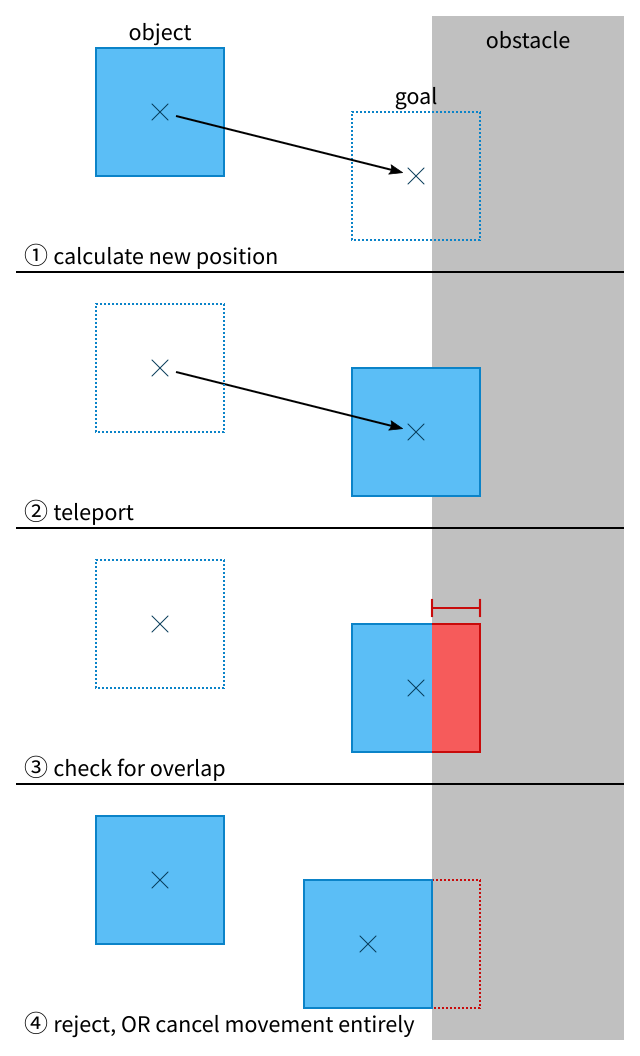
(Note that all of these diagrams show very exaggerated motion. In most games, objects are slow and frames are short, so nothing moves more than a pixel or two at a time. That’s another reason collision detection is hard: the steps are so small that it can be difficult to see what’s actually going on.)
If it does overlap, you might might try to push it out of whatever it’s overlapping, or you might cancel the movement entirely and simply not move the object that frame.
Both approaches have drawbacks. Pushing an object out of an obstacle isn’t too difficult a problem, but it’s possible that the object will be pushed out into another obstacle, and now you have a complicated problem. (At this point, though, you could just give up and fall back to cancelling the movement.)
But cancelling the movement means that an object might get “stuck” a pixel or two away from a wall and never be able to butt up against it. The faster the object is trying to move, the bigger the risk that this might happen.
That said, this is exactly how the original Doom engine handles collision, and it seems to work well enough there. On the other hand, Doom is first-person so you can’t easily tell if you’re butting right up against a wall; a pixel gap is far more obvious in a game like this. On the other other hand, Doom also has bugs where a fast monster can open a locked door from its other side, because the initial teleport briefly moves the monster far enough into the door that it’s touching the other (unlocked) side.
Sorry. I have very conflicting feelings about this thicket of drawbacks and possible workarounds.
Either way, discrete collision has one other big drawback: tunnelling. Since the movement is done by teleporting, a very fast object might teleport right past a thin barrier. Only the new position is checked for collisions, so the barrier is never noticed. (This is how you travel to parallel universes in Mario 64 — by building up enough speed that Mario teleports through walls without ever momentarily overlapping them.)
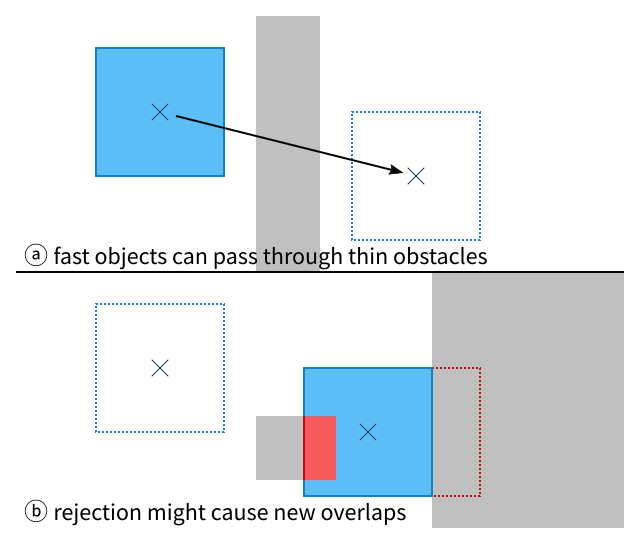
There are some other potential gotchas, though they’re rare enough that I’ve never seen anyone mention them. One that stands out to me is that you don’t know the order that an object collided with obstacles, which might make a difference if the obstacles have special behavior when collided with and the order of that behavior matters.
Continuous collision detection observes that game physics are trying to simulate continuous motion, like happens in the real world, and tries to apply that to movement as well. Instead of teleporting, objects slide until they hit something. Tunnelling is thus impossible, and there’s no need to handle collisions since they’re prevented in the first place.
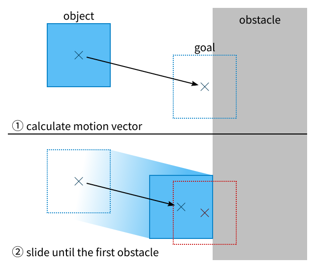
This has some clear advantages, in that it eliminates all the pitfalls of discrete collision! It even functions as a superset — if you want some object to act discretely, you could simply teleport it and then attempt to “move” it along the zero vector.
That said, continuous collision introduces some of its own problems. The biggest (for my purposes, anyway) is that it’s definitely more complicated to implement. “Sliding” means figuring out which obstacle would be hit first. You can do raycasting in the direction of movement and see what the ray hits first, though that’s imprecise and opens you up to new kinds of edge cases. If you’re lucky, you’re using something like Unity and can cast the entire shape as a single unit. Otherwise, well, you have to do a bunch of math to find everything in the swept path, then sort them in the order they’d be hit.
The other big problem is that it’s more work at runtime. With discrete collision, you only need to check for collisions in the new location. That only costs more time when a lot of objects are bunched together in one place, which is unlikely. With continuous collision, everything along the swept path needs to be examined, and that means that the faster an object moves, the more expensive its movement becomes.
So, not quite a golden bullet for the tunnelling problem. But that’s not a surprise; the only way to prevent tunnelling is to check for objects between the start and end positions.
Which, then, do I want to implement here?
For platforms without floating point (including the PICO-8 and Game Boy), there’s a third, hybrid option. If everything’s expressed with integers (or fixed point), then the universe has a Planck length: a minimum distance that every other distance must be an integral multiple of. You can thus fake continuous collision by doing repeated steps of discrete collision, one Planck length at a time. Objects will be collided with in the correct order, and you can simply stop at the first overlap.
Of course, this eats up a lot of time, since it involves doing collision detection numerous times per object per frame. So unless your Planck length is really big, I’m not sure it’s worth it.
Instead, I’m going to try for continuous collision. It’s closer to “correct” (whatever that means), and it’s what I did for all of my other games so far. It’s definitely harder, thornier, more complicated, and slower, but dammit I like it. It should also save me from encountering surprise bugs later on, which means I can write collision code once and then pretty much forget about it. Ideal.
Getting started
Star Anise is the only entity at the moment, so as a first pass, I’m only going to implement collision with the world.
World collision is much easier! Everything is laid out in a fixed grid, so I already know where the cells are. Finding potential overlaps is fairly simple, and best of all, I don’t need to sort anything to know what order the cells are in.
Right away, I find I have another decision to make. I would normally want to use vector math here — the motion is some distance in some direction, and hey, that’s a vector. But vectors take up twice as much space (read: twice as many registers), and a lot of vector operations rely on division or square roots which are non-trivial on this hardware.
With a great reluctant sigh, I thus commit to one more approximation, one made on 8-bit hardware since time immemorial. I won’t actually move in the direction of motion; instead, I’ll move along the x-axis, then move along the y-axis separately. Diagonal movement could theoretically cut across some corners (or be unable to fit through very tight gaps), but those are very minor and unlikely inconveniences. More importantly, this handwaving can’t allow any impossible motion.
I’ve already taken for granted that entities will all be axis-aligned rectangles. I’m definitely not dealing with slopes on a goddamn Game Boy. That was hard enough to do from scratch on a modern computer.
But I’m getting ahead of myself. First things first: you may recall that Star Anise’s movement is a bit of a hack. Pressing a direction button only adds to or subtracts from the sprite coordinates in the OAM buffer; his position isn’t actually stored in RAM anywhere. In fact, thanks to my slightly nonlinear storytelling across these posts, his movement isn’t stored anywhere either! The input-reading code writes directly to the OAM buffer. Whoops. I intended to fix that later, and now it’s later, so here we go.
1; Somewhere in RAM, before anise_facing etc
2anise_x:
3    db
4anise_y:
5    db
So far, so good. OAM is populated in two places (and I should fix that later, too): once during setup, and once in the main game loop. Both will need to be updated to use these values.
Setup needs to initialize them first, of course:
1    ld a, 64
2    ld [anise_x], a
3    ld [anise_y], a
4    ; ... initialize anise_facing, etc ...
And now the OAM setup can be fixed. But, surprise! I left myself another hardcoded knot to untangle: even the relative positions of the sprites are hardcoded. Okay, so, those need to be put somewhere too. Eventually I’m going to need some kinda entity structure, but since there’s only one entity, I’ll just slap it into a constant somewhere.
(I guess my programming philosophy is leaking out a bit here. Don’t worry about structure until you need it, and you don’t need it until you need it twice. Once code works for one thing, it’s relatively straightforward to make it work for n things, and you have fewer things to worry about while you’re just trying to make something work.)
1; In ROM somewhere
2ANISE_SPRITE_POSITIONS:
3    db -2, -20
4    db -8, -14
5    db 0, -14
It’s not immediately obvious from looking at these numbers, but I’m taking Star Anise’s position to mean the point on the ground between his feet. That’s the best approximation of where he is, after all.
(Early in game development, it seems natural to treat position as the upper-left corner of the sprite, so you can simply draw the sprite at the entity’s position — but that tangles the world model up with the sprite you happen to have at the moment. Imagine the havoc it’d wreak if you changed the size of the sprite later!)
Okay, now I can finally—
What? How does the code know there are exactly 3 sprites, on this byte-level platform? Because I’m hardcoding it. Shut up already I’ll fix it later
 1    ; Load the x and y coordinates into the b and c registers
 2    ld hl, anise_x
 3    ld b, [hl]
 4    inc hl
 5    ld c, [hl]
 6    ; Leave hl pointing at the sprite positions, which are
 7    ; ordered so that hl+ will step through them correctly
 8    ld hl, ANISE_SPRITE_POSITIONS
 9
10    ; ANTENNA
11    ; x-coord
12    ; The x coordinate needs to be added to the sprite offset,
13    ; AND the built-in OAM offset (8, 16).  Reading the sprite
14    ; offset first allows me to use hl+.
15    ld a, [hl+]
16    add a, b
17    add a, 8
18    ; Previously, hl pointed into the OAM buffer and advanced
19    ; throughout this code, but now I'm using hl for something
20    ; else, so I use direct addresses of positions within the
21    ; buffer.  Obviously this is a kludge and won't work once
22    ; I stop hardcoding sprites' positions in OAM, but, you
23    ; know, I'll fix it later.
24    ld [oam_buffer + 1], a
25    ; y-coord
26    ld a, [hl+]
27    add a, c
28    add a, 16
29    ld [oam_buffer + 0], a
30    ; This stuff is still hardcoded.
31    ; chr index
32    xor a
33    ld [oam_buffer + 2], a
34    ; attributes
35    ld [oam_buffer + 3], a
36
37    ; The rest of this is not surprising.
38
39    ; LEFT PART
40    ; x-coord
41    ld a, [hl+]
42    add a, b
43    add a, 8
44    ld [oam_buffer + 5], a
45    ; y-coord
46    ld a, [hl+]
47    add a, c
48    add a, 16
49    ld [oam_buffer + 4], a
50    ; chr index
51    ld a, 2
52    ld [oam_buffer + 6], a
53    ; attributes
54    ld a, %00000001
55    ld [oam_buffer + 7], a
56
57    ; RIGHT PART
58    ; x-coord
59    ld a, [hl+]
60    add a, b
61    add a, 8
62    ld [oam_buffer + 9], a
63    ; y-coord
64    ld a, [hl+]
65    add a, c
66    add a, 16
67    ld [oam_buffer + 8], a
68    ; chr index
69    ld a, 4
70    ld [oam_buffer + 10], a
71    ; attributes
72    ld a, %00000001
73    ld [oam_buffer + 11], a
Boot up the game, and… it looks the same! That’s going to be a running theme for a little bit here. Sorry, this isn’t a particularly screenshot-heavy post. It’s all gonna be math and code for a while.
Now I need to split apart the code that reads input and applies movement to OAM. Reading input gets much simpler, since it doesn’t have to do anything any more, just compute a dx and dy.
This code does still have looming questions, such as how to handle pressing two opposite directions (which is impossible on hardware but easy on an emulator), or whether diagonal movement should be fixed so that Anise doesn’t move at \(\sqrt{2}\) his movement speed.
Later. Seriously the actual code has so many XXX and TODO and FIXME comments that I edit out of these posts.
 1    ; Anise update loop
 2    ; Stick dx and dy in the b and c registers.
 3    ld a, [buttons]
 4    ; b/c: dx/dy
 5    ld b, 0
 6    ld c, 0
 7    bit PADB_LEFT, a
 8    jr z, .skip_left
 9    dec b
10.skip_left:
11    bit PADB_RIGHT, a
12    jr z, .skip_right
13    inc b
14.skip_right:
15    bit PADB_UP, a
16    jr z, .skip_up
17    dec c
18.skip_up:
19    bit PADB_DOWN, a
20    jr z, .skip_down
21    inc c
22.skip_down:
23
24    ; For now just add b and c to Anise's coordinates.  This
25    ; is where collision detection will go in a moment!
26    ld a, [anise_x]
27    add a, b
28    ld [anise_x], a
29    ld a, [anise_y]
30    add a, c
31    ld [anise_y], c
All that’s left is to more explicitly update the OAM buffer!
This code ends up looking fairly similar to the setup code. So similar, in fact, that I wonder if these blocks should be merged, but I’ll do that later:
 1    ; Load x and y into b and c
 2    ld hl, anise_x
 3    ld b, [hl]
 4    inc hl
 5    ld c, [hl]
 6    ; Point hl at the sprite positions
 7    ld hl, ANISE_SPRITE_POSITIONS
 8
 9    ; ANTENNA
10    ; x-coord
11    ld a, [hl+]
12    add a, b
13    add a, 8
14    ld [oam_buffer + 1], a
15    ; y-coord
16    ld a, [hl+]
17    add a, c
18    add a, 16
19    ld [oam_buffer + 0], a
20    ; LEFT PART
21    ; x-coord
22    ld a, [hl+]
23    add a, b
24    add a, 8
25    ld [oam_buffer + 5], a
26    ; y-coord
27    ld a, [hl+]
28    add a, c
29    add a, 16
30    ld [oam_buffer + 4], a
31    ; RIGHT PART
32    ; x-coord
33    ld a, [hl+]
34    add a, b
35    add a, 8
36    ld [oam_buffer + 9], a
37    ; y-coord
38    ld a, [hl+]
39    add a, c
40    add a, 16
41    ld [oam_buffer + 8], a
Phew! And the game plays exactly the same as before. Programming is so rewarding.
On to the main course!
Collision detection, sort of
So. First pass. Star Anise can only collide with the map.
Ah, but first, what size is Star Anise himself? I’ve only given him a position, not a hitbox. I could use his sprite as the hitbox, but with his helmet being much bigger than his body, that’ll make it seem like he can’t get closer than a foot to anything else. I’d prefer if he had an explicit radius.
1; in ROM somewhere
2ANISE_RADIUS:
3    db 3
Remember, Star Anise’s position is the point between his feet. This describes his hitbox as a square, centered at that point, with sides 6 pixels long. The top and bottom edges of his hitbox are thus at y - r and y + r, which makes for some pleasing symmetry.
(Making hitboxes square doesn’t save a lot of effort or anything, but switching to rectangles later on wouldn’t be especially difficult either.)
The plan
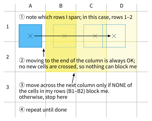
My plan for moving rightwards, which I came up with after a lot of very careful and very messy sketching, looks like this:
-
Figure out which rows I’m spanning.
-
Move right until the next grid line. No new obstacle can possibly be encountered until then, so there’s nothing to check.
(Unless I’m somehow already overlapping an obstacle, of course, but then I’d rather be able to move out of the obstacle than stay stuck and possibly softlock the game.)
-
In the next grid column, check every cell that’s in a spanned row. If any of those cells block us, stop here. Otherwise, move to the next grid line (8 pixels).
-
Repeat until I run out of movement.
(It’s very unlikely the previous step would happen more than once; an entity would have to move more than 8 pixels per frame, which is 3 entire screen widths per second.)
Here’s a diagram. In this case, step 3 checks two cells for each column, but it might check more or fewer depending on how the entity is positioned. (It’ll never need to check more than one cell more than the entity’s height.)
Seems straightforward enough. But wait!
Edge case
I’ll save you a bunch of debugging anguish on my part and skip to the punchline: there’s an edge case.
I mean, literally, the case of when the entity’s edge is already against a grid line. That’ll happen fairly frequently — every time an entity collides with the map, it’ll naturally stop with its edge aligned to the grid.
The problem is all the way back in step 1. Remember, I said that to figure out which grid row or column a point belongs to, I need to divide by 8 (or shift right by 3). So the rows an entity spans must count from its top edge divided by 8, to its bottom edge divided by 8. Right?
Well…
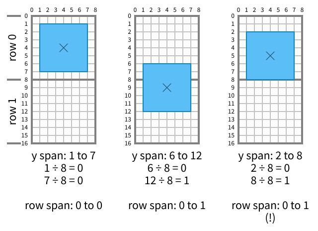
Everything’s fine until the entity’s bottom edge is exactly flush with the grid line, as in the last example. Then it seems to be jutting into the row below, even though no part of it is actually inside that row. If the entity tried to move rightwards from here, it might get blocked on something in row 1! Even worse, if row 1 were a solid wall that it had just run into, it wouldn’t be able to move left or right at all!
What happened here? There’s a hint in how I laid out the diagram.
There’s something akin to the fencepost problem here. I’ve been talking about rows and columns of the grid as if they were regions — “row 1” labels a rectangular strip of the world. But pixel coordinates don’t describe regions! They describe points. A pixel is a square area, but a pixel coordinate is the point at the upper left corner of that area.
In the incorrect example, the bottom of the entity is at y = 8, even though the row of pixels described by y = 8 doesn’t contain any part of the hitbox. I’m using the coordinate of the pixel’s top edge to describe a box’s bottom edge, and it falls apart when I try to reinterpret that coordinate as a region. In terms of area, y = 8 really names the first row of pixels that the entity doesn’t overlap.
To work around this, I need to adjust how I convert a coordinate to the corresponding grid cell, but only when that coordinate describes the right or bottom of a bounding box. Bottom pixel 8 should belong to row 0, but 9 should still end up in row 1.
As luck would have it, I’m using integers for coordinates, which means there’s a Planck length — a minimum distance of which all other distances are a multiple. That length is, of course, 1 pixel. If I subtract that length from a bottom coordinate, I get the next nearest coordinate going upwards. If the original coordinate was on a grid line, it’ll retreat back into the cell above; otherwise, it’ll stay in the same cell. You can check this with the diagram, if you need some convincing.
(This works for any fixed point system; integers are the special case of fixed point with zero fractional bits. It would not work so easily with floating point — subtracting the smallest possible float value will usually do nothing, because there’s not enough precision to express the difference. But then, if you have floating point, you probably have division and can write vector-based collision instead of taking grid-based shortcuts.)
All that is to say, I just need to subtract 1 before shifting. For clarity, I’ll write these as macros to convert a coordinate in a to a grid cell. I call the top or left conversion inclusive, because it includes the pixel the coordinate refers to; conversely, the bottom and right conversion is exclusive, like how a bottom of 8 actually excludes the pixels at y = 8.
 1; Given a point on the top or left of a box, convert it to the
 2; containing grid cell.
 3ToInclusiveCell: MACRO
 4    ; This is just floor division
 5    srl a
 6    srl a
 7    srl a
 8ENDM
 9; Given a point on the bottom or right of a box, convert it to
10; the containing grid cell.
11ToExclusiveCell: MACRO
12    ; Deal with the exclusive edge by subtracting the planck
13    ; length, then flooring
14    dec a
15    srl a
16    srl a
17    srl a
18ENDM
At last, I can write some damn code!
Some damn code
 1    ; Here, b and c contain dx and dy, the desired movement.
 2
 3    ; First, figure out which columns we might collide with.
 4    ; The NEAREST is the first one to our right that we're not
 5    ; already overlapping, i.e. the one /after/ the one
 6    ; containing our right edge.  That's Exc(x + r) + 1.
 7    ; The FURTHEST is the column that /will/ contain our right
 8    ; edge.  That's Exc(x + r + dx).
 9    ld hl, ANISE_RADIUS
10    ; Put the NEAREST column in d
11    ld a, [anise_x]             ; a = x
12    add a, [hl]                 ; a = x + r
13    ld e, a                     ; e = x + r
14    ToExclusiveCell
15    inc a                       ; a = Exc(x + r) + 1
16    ld d, a                     ; d = Exc(x + r) + 1
17    ; Put the FURTHEST column in e
18    ld a, e                     ; a = x + r
19    add a, b                    ; a = x + r + dx
20    ToExclusiveCell
21    ld e, a                     ; e = Exc(x + r + dx)
22
23    ; Loop over columns in [d, e].
24    ; If d > e, this movement doesn't cross a grid line, so
25    ; nothing can stop us and we can skip all this logic.
26    ld a, e
27    cp d
28    jp c, .done_x
29    ; We don't need dx for now, so stash bc for some work space
30    push bc
31.x_row_scan:
32    ; For each column we might cross: check whether any of the
33    ; rows we span will block us.
34    ; Hm.  This code probably should've been outside the loop.
35    ld a, [anise_y]
36    ld hl, ANISE_RADIUS
37    sub a, [hl]
38    ToInclusiveCell
39    ld b, a                     ; b = minimum y
40    ld a, [anise_y]
41    add a, [hl]
42    ToExclusiveCell
43    ld c, a                     ; c = maximum/current y
44
45.x_column_scan:
46    ; Put the cell's row and column in bc, and call a function
47    ; to check its "map flags".  I'll define that in a moment,
48    ; but for now I'll assume that if bit 0 is set, that means
49    ; the cell is solid.
50    ; This is also why the inner loop counts down with c, not
51    ; up with b: get_cell_flags wants the y coord in c, and
52    ; this way, it's already there!
53    push bc
54    ld b, d
55    call get_cell_flags
56    pop bc
57    ; If this produces zero, we can skip ahead
58    and a, $01
59    jr z, .not_blocked
60
61    ; We're blocked!  Stop here.  Set x so that we're butted
62    ; against this cell, which means subtract our radius from
63    ; its x coordinate.
64    ; Note that this can't possibly move us further than dx,
65    ; because dx was /supposed/ to move us INTO this cell.
66    ld a, d
67    ; This is a /left/ shift three times, for cell -> pixel
68    sla a
69    sla a
70    sla a
71    sub a, [hl]
72    ld [anise_x], a
73    ; Somewhat confusing pop, to restore dx and dy.
74    pop bc
75    jp .done_x
76
77.not_blocked:
78    ; Not blocked, so loop to the next cell in this column
79    dec c
80    ld a, c
81    cp b
82    jr nc, .x_column_scan
83
84    ; Finished checking one column successfully, so continue on
85    ; to the next one
86    inc d
87    ld a, e
88    cp d
89    jr nc, .x_row_scan
90
91    ; Done, and we never hit anything!  Update our position to
92    ; what was requested
93    pop bc
94    ld a, [anise_x]
95    add a, b
96    ld [anise_x], a
I’ve also gotta implement get_cell_flags, which is slightly uglier than I anticipated.
 1; Fetches properties for the map cell at the given coordinates.
 2; In: bc = x/y coordinates
 3; Out: a = flags
 4get_cell_flags:
 5    push hl
 6    push de
 7    ; I have to figure out what char is at these coordinates,
 8    ; which means consulting the map, which means doing math.
 9    ; The map is currently 16 (big) tiles wide, or 32 chars,
10    ; so the byte for the indicated char is at b + 32 * c.
11    ld hl, TEST_MAP_1
12    ; Add x coordinate.  hl is 16 bits, so extend b to 16 bits
13    ; using the d and e registers separately, then add.
14    ld d, 0
15    ld e, b
16    add hl, de
17    ; Add y coordinate, with stride of 32, which we can do
18    ; without multiplying by shifting left 5.  Alas, there are
19    ; no 16-bit shifts, so I have to do this by hand.
20    ; First get the 5 high bits by copying y into d, then
21    ; shifting the 3 low bits off the right end.
22    ld d, c
23    srl d
24    srl d
25    srl d
26    ; Then get the low 3 bits into the high 3 by swapping,
27    ; shifting, and masking them off.
28    ld a, c
29    swap a
30    sla a
31    and a, $e0
32    ld e, a
33    ; Not sure that was really any faster than just shifting
34    ; left through the carry flag 5 times.  Oh well.  Add.
35    add hl, de
36
37    ; At last, we know the char.  I don't have real flags at
38    ; the moment, so I just hardcoded the four chars that make
39    ; up the small rock tile.
40    ld a, [hl]
41    cp a, 2
42    jr z, .blocking
43    cp a, 3
44    jr z, .blocking
45    cp a, 12
46    jr z, .blocking
47    cp a, 13
48    jr z, .blocking
49    jr .not_blocking
50    ; The rest should not be too surprising.
51.blocking:
52    ld a, 1
53    jr .done
54.not_blocking:
55    xor a
56.done:
57    pop de
58    pop hl
59    ret
And that’s it!
That's not it
The code I wrote only applies when moving right. It doesn’t handle moving left at all.
And here I run into a downside of continuous collision, at least in this particular case. Because of the special behavior of right/bottom edges, I can’t simply flip a sign to make this code work for leftwards movement as well. For example, the set of columns I might cross going rightwards is calculated exclusively, because my right edge is the one in front… but if I’m moving leftwards, it’s calculated inclusively. Those columns are also in reverse order and thus need iterating over backwards, so an inc somewhere becomes a dec, and so on.
I have two uncomfortable options for handling this. One is to add all the required conditional tests and jumps, but that adds a decent CPU cost to code that’s fairly small and potentially very hot, and complicates code that’s a bit dense and delicate to begin with. The other option is to copy-paste the whole shebang and adjust it as needed to go leftwards.
Guess which I did!
1    ld a, b
2    cp a, $80
3    jp nc, .negative_x
4.positive_x:
5    ; ... everything above ...
6    jp .done_x
7.negative_x:
8    ; ... everything above, flipped ...
9.done_x:
Ugh. Don’t worry, though — it gets worse later on!
I could copy-paste for y movement too and give myself a total of four blocks of similar code, but I’ll hold off on that for now.
…
Ah.
You want the payoff, don’t you.
Well, I’m warning you now: the next post gets much hairier, and if I show you a GIF now, there won’t be any payoff next time.
You sure? Really?
No going back!

I admit, this was pretty damn satisfying the first time it actually worked. Collision detection is a pain in the ass, but it’s the first step to making a game feel like a game. Games are about working within limitations, after all!
An aside: debugging
I’ve made this adventure seem much easier than it actually was by eliding all the mistakes. I made a lot of mistakes, and as I said upfront, it can be very difficult to notice heisenbugs or figure out exactly what’s causing them.
One thing that helped tremendously near the beginning was to hack Star Anise to have a fourth sprite: a solid black 6×6 square under his feet. That let me see where he was actually supposed to be able to stand. Highly recommend it. All I did was copy/paste everywhere that mentioned his sprites to add a fourth one, and position it centered under his feet.
(On any other system, I’d just draw collision rectangles everywhere, but the Game Boy is sprite-based so that’s not really gonna fly.)
I also had pretty good success with writing intermediate values to unused bytes in RAM, so I could inspect them in mGBA’s memory viewer even after the movement was finished. And of course, as an absolute last resort, bgb has an interactive graphical debugger. (Nothing against bgb per se; I just prefer not to rely on closed-source software running in Wine if I can at all get away with it.)
To be continued
Obviously, this isn’t anywhere near done. There’s no concept of collision with other entities, and before that’s even a possibility, I need a concept of other entities. I left myself a long trail of do-it-laters. There are even risks of overflow and underflow in a couple places, which I didn’t bother pointing out because I completely overhaul this code later.
But it’s a big step forward, and now I just need a few more big steps forward. (I say, four months later, long after all those steps are done.)
I already have some future ideas in mind, like: what if a map tile weren’t completely solid, but had its own radius? Could I implement corner cutting, where the game gently guides you if you get stuck on a corner by only a single pixel? What about having tiles that are 45° angles, just to cut down on the overt squareness of the map?
Well. Maybe, you know, later.
Anyway, that brings us up to commit da7478e. It’s all downhill from here.
Next time: more collision detection, and fixed-point arithmetic!

![[process]](https://eev.ee/theme/images/category-process.png)
